|
FEATURES
- Enables phased introduction of Surface Mount Technology - SMT.
- Permits use of mixed technology - plated through hole (PTH) + SMT.
- Simplifies handling and test.
- Increases space utilization of available component area.
- Provides a modular approach to design and manufacture.
Reduces equipment downtime by simplifying fault location.
|
An Introduction to H.I.T.
Advances in Surface Mount Technology (SMT), Very Large Scale Integration (VLSI), Tape
Automated Bonding (TAB) and other comparable technologies has led to significant increases
in packaging densities over recent years. With SMT for example, three fold increases in
packing density can now be expected compared to conventional p.c.b. methods.
Whatever the merits of these advances, they can nevertheless present formidable
difficulties not only in terms of assembly and diagnostic testing, but also reworking.
Complexities aside, costs can be considerable.
Effects of these technologies in introducing sizeable increases in complexity, cost and
test problems can often discourage any policy of standardizing on large p.c.b.'s. This can
conflict with well established equipment practices such as those effecting equipment for
which Double Eurocards are extensively used as an example. Moreover, in many industry
sectors, adoption of total surface mount p.c.b.'s can lead to unacceptably high levels of
initial capital investment and engineering effort.
A controlled and phased introduction of SMT in parallel with conventional thru-hold
solder technology therefore presents a more viable approach to these difficulties. As such
it has led to the development of an entirely new interconnection system and equipment
practice; Hierarchical Interconnection Technology or HIT.
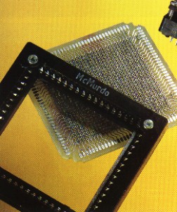
The H.I.T. Concept
In effect, HIT produces a framework for circuit board partitioning and modularization as
well as solderless assembly of sub-units. At the same time, it also enables engineers to
continue to base their designs on large boards and established equipment practices.
The system is based on circuit units that are intermediate in size between a
conventional p.c.b. (Daughter Board) and chipcarrier. Units assume the form of small
boards (Child Boards) that are "socketed" into the HIT connector which is then
parallel mounted onto the Daughter Board. The connector is also designed to be capable of
using a variety of substrate materials. Thus single-sided, double-sided and multilayer
boards using glass-epoxy, metal clad laminates or ceramic substrates can all be
accommodated.
This therefore permits the use of mixed technologies enabling the phased introduction
of SMT into conventional technology. Similarly if redesign or updating is required, this
can be confined to the module rather than involving the entire board.
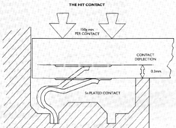
The H.I.T. CONTACT
Two essential requirements which had to be met were (a) High reliability
and (b) Low installed costs to satisfy these needs.
HIT uses two basic elements; a connector and a clamp. The connector
consists of an insulator fitted with cantilever contacts with straight p.c. terminations.
The clamp provides the contact pressure being secured by captive screws engaging captive
threaded inserts in the insulator.
| The contact system provides a small wiping action between the contact and
the child board pad as the clamp is secured. The clamp is secured to a datum on the
insulator such that a minimum contact pressure of 150g is achieved. Thus it is possible to
avoid precious metal plating and use tin-lead, as a reliable gas-tight joint is achieved.
Extensive testing, has proved this to be so even after the child board and connector have
been subjected to 100 operations. A detailed Equipment Practice which includes data on
thermal management, EMC etc. is available on request. |
 |
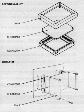
Two Versions of HIT are Available - Rectangular HIT and
Linear HIT
| RECTANGULAR HIT has been designed to optimize the space
available on a Double Eurocard daughter board. Two sizes are offered, Size A (128
contacts) and Size B (204 contacts). Eight Size A or four Size B connectors ( or a mixture
of both) can be accommodated. Using Surface Mount components both sides of the child board
can be populated. The clearance between the underside of the child board and topside of
the daughter board is 4.35mm. The child board is polarized. LINEAR HIT
provides the opportunity for the child boards to be of variable lengths and widths and is
available in three sizes, 16, 32, and 64 way. The standard clearance between child board
and daughter board is increased to 6.35mm permitting thru board or surface mount
components to also be mounted on the daughter board. In addition, the 32 and 64 way sizes
can also be supplied with a 10mm clearance to cater for larger size components, along the
surface of the p.c.b. The Linear HIT may be edge mounted or in-board mounted and can be
polarized in a number of alternative positions in respect of the child board. |
 |
TECHNICAL
DATA
MATERIALS
| Insulator Size A & B |
PPS thermoplastic rated UL94V-0 |
| Linear |
PET glass filled polyester rated UL94V-0 |
| Contact |
Copper alloy plated tin/lead or hard acid gold |
| Termination |
Tin lead |
| Clamps |
Zinc/alloy or aluminum chromate passivate |
| Clamp screws |
Steel/zinc plated |
MECHANICAL
| Mechanical operations |
100 |
| Child boards |
Accomodates laminate p.c.b.'s between 0.95mm and 2.0mm thickness. HIT Size
A and B will also accept ceramic substrates of 1.00mm thickness. |
|
|
ENVIRONMENTAL
| Climate category |
55/125/56 |
| Vibration severity |
10-2000Hz, 0.75mm/98m/s�(10gn) duration 6h |
| Bump severity |
390m/s� (40gn), 4000�10 |
| Shock severity |
490m/s� (50gn), for 11ms. |
ELECTRICAL
| Current |
|
| Individual contact (in isolation) |
at 85�C Tamb. 2A max. |
| All contacts simultaneously |
at 85�C Tamb. 1.4A max. |
| Working Voltage |
350Vd.c. or a.c. peak |
| Proof Voltage |
1000 Vd.c. or a.c. peak |
| Contact Resistance (initially) |
15mohm max. |
| Contact Resistance (after conditioning) |
20mohm max. |
| Insulation Resistance (initially) |
1000Mohm min. |
| Insulation Resistance (after conditioning |
100Mohm min. |
|
ORDERING INFORMATION - RECTANGULAR HIT
|
S1234 |
B |
204 |
T1 |
000 |
| SERIES------------------------------------------------------ |
| |
| |
| |
| |
| |
| SIZE---------------------------------------------------------- |
-------- |
| |
| |
| |
| |
| CONTACT
ARRANGEMENTS---------------------- |
-------- |
-------- |
| |
| |
| |
| TERMINATION
STYLE-------------------------------- |
-------- |
-------- |
-------- |
| |
| |
| VARIANT
--------------------------------------------------- |
-------- |
-------- |
-------- |
------- |
| |
SERIES
S1234 - Rectangular HIT
SERIES
A - Size A module
B - Size B module
CONTACT ARRANGEMENT
128 - Size A
204 - Size B |
CONTACT PITCH A
- 2.54mm ALL FILLED
E - 5.08mm EVEN ONLY FILLED
PRE-MATING CONTACTS
N - None fitted
No designator (BS styles) - None fitted
P - Fitted positions a1 & a16 (32 & 48 mould size)
Fitted positions a1 & a32 (64 & 96 mould size)
TERMINATION
L1, L2, L3, L4, L5 & L6 - Male contacts
S0, T1, T2, T3, T4, T5, W1, & W2 - Female contacts
|
ORDERING INFORMATION (Reverse DIN 41612)
|
RIM |
96 |
64 |
5 |
A |
P |
TI |
G |
H |
| SERIES/GENDER----------------------------- |
| |
| |
| |
| |
| |
| |
| |
| |
| |
| MOULD SIZE---------------------------------- |
-------- |
| |
| |
| |
| |
| |
| |
| |
| |
| No. OF CONTACTS-------------------------- |
-------- |
-------- |
| |
| |
| |
| |
| |
| |
| |
| CONTACT LOADING----------------------- |
-------- |
-------- |
-------- |
| |
| |
| |
| |
| |
| |
| CONTACT PITCH---------------------------- |
-------- |
-------- |
-------- |
------- |
| |
| |
| |
| |
| |
| PRE-MATING CONTACTS---------------- |
-------- |
-------- |
-------- |
------- |
------- |
| |
| |
| |
| |
| TERMINATION STYLE-------------------- |
-------- |
-------- |
-------- |
------- |
------- |
------- |
| |
| |
| |
| CONTACT FINISH--------------------------- |
-------- |
-------- |
-------- |
------- |
------- |
------- |
------- |
| |
| |
| TERMINATION FINISH------------------- |
-------- |
-------- |
-------- |
------- |
------- |
------- |
------- |
--- |
| |
BS SERIES
B5412 - BS9525 F0017 - Fixed male
B5413 - BS9525 F0017 - Free female
B5532 - BS9525 F002 - Fixed male
B5533 - BS9525 F0032 - Free female
SERIES/GENDER
QIF - Reverse DIN 2 row female
QIM - Reverse DIN 2 row male
RIF - Reverse DIN 3 row female
RIM - Reverse DIN 3 row male
MOULD SIZE
64 - 2 rows of 32 (Q)
96 - 3 rows of 32 (R)
No. OF CONTACTS
16, 32, 48, 64, & 96
CONTACT LOADING
1 - Row a only
2 - Row b only
3 - Row c only
4 - Rows a & b
5 - Rows a & c
6 - Rows b & c
7 - Rows a, b, & c
0 - All Rows (BS style)
X - Special loading |
CONTACT PITCH A
- 2.54mm ALL FILLED
E - 5.08mm EVEN ONLY FILLED
PRE-MATING CONTACTS
N - None fitted
No designator (BS styles) - None fitted
P - Fitted positions a1 & a16 (32 & 48 mould size)
Fitted positions a1 & a32 (64 & 96 mould size)
TERMINATION
T1, T2, T5, T5, T6, T8, W1, & W2 - Male contacts
L1, L2, L3, L4, L5 & L6 - Female contacts
CONTACT FINISH
G - Class 1
L - Class 2
Q - Class 3
TERMINATION FINISH
H - Tinned
I - Tinned
|