![]()
 The Microconnector Series 200, two part printed circuit board
connector system utilizes a 2mm (0.8in) pitch and has been specifically designed for use
as a low voltage connector in high density packaging electronic equipment, particularly
where military environmental classifications are to be met.
The Microconnector Series 200, two part printed circuit board
connector system utilizes a 2mm (0.8in) pitch and has been specifically designed for use
as a low voltage connector in high density packaging electronic equipment, particularly
where military environmental classifications are to be met.
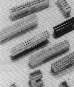
The product has a low profile of only 10mm nom. over the mated pair from p.c. to the terminations and provides a small footprint to increase packaging density. It is 180° polarized and at the same time fully shrouded to protect otherwise vulnerable micro-miniature contacts.
It is avialable as either a single row (Series 201) providing a 2 to 17 ways in 7 sizes or a two row (Series 202) providing 4 to 34 ways in 11 sizes.
Male connectors may have either straight or 90 ° p.c. terminations suitable for printed boards of 1.6mm nom. thickness. Connector retaining straps are fitted to provide adequate rigidity when mounted and mating latches are available as an option.
Female connectors may have either a straight p.c. termination for use with printed boards or printed wiring, or a choice of two sizes of crimp for use with discrete wires.
The socket contact is of precision two part construction having an outer shell fitted with an inner four-leaf contact with symmetrical short conatilever beams arranged in a radially opposing system.
Provision has been made for tooling for crimp contacts, to insert and withdraw the crimped contact from the moulding and de-latch and separated the mated connectors.
![]()
| Mouldings | Glass filled polyester rated UL94-V-O |
| Contacts - Male | Phosphor bronze |
| Contacts - Female | Inner - Beryllium copper, Outer - Brass |
| Contact Finish | Hard acid gold |
| Latches | Beryllium copper |
| Latch Finish | Nickel |
| Climatic category | 55/125/56 |
| Vibration severity (General) | 10Hz, 2000Hz; 0.75mm/98m/s(2) (10gn) duration 6h |
| Vibration severity (Additional) | 13.3Hz to 2000Hz random with superimposed sinusoids, duration 15 min each of 4 planes. No intermittancies measured when using an H.S.L.I. (High Speed Logic Interrupt) detector with a trip threshold of 2ns |
| Bump severity | 390m/s(2) (40gn) 4000+- 10 bumps |
| Shock severity | 981 m/s(2) (100gn), for 6ms |
| Acceleration severity | 490m/s(2) |
| Mechanical operations | 500 operations (Full assessment) |
| Insertion and withdrawal force (per contact pair) | 0.8N max. 0.2N min. |
| Contact retention | 10N min. |
| Crimp barrell accommodation | 22 AWG - 28 AWG to BS G 210 type A |
| Current | |
| Individual contacts (in isolation) | At 25°C Tamb. 2A max. |
| Individual contacts (in isolation) | At 85°C Tamb. 1.75A max. |
| All contacts simultaneously | At 25°C Tamb. 1.75A max. |
| All contacts simultaneously | At 85°C Tamb. 1.5A max. |
| Working Voltage (at sea level 1013 mbar) | 120V d.c. or a.c. peak |
| Proof Voltage (at sea level 1013 mbar) | 360V d.c. or a.c. peak |
| Contact resistance (initially) | 20mohm max. |
| Contact resistance (after conditioning) | 25mohm max. |
| Insulation resistance (initially) | 1000 Mohm min. |
| Insulation resistance (after conditioning) | 100 Mohm min. |
![]()
![]()
Outlline Deimensions
|
Pin Numbering
|
| Contact Arrangement Single Row | 2 | 3 | 4 | 5 | 6 | 7 | - | - | - | - | 17 |
| Contact Arrangement Two Row | 4 | 6 | 8 | 10 | 12 | 14 | 16 | 18 | 20 | 26 | 34 |
| A | 2.00 | 4.00 | 6.00 | 8.00 | 10.00 | 12.00 | 14.00 | 16.00 | 18.00 | 24.00 | 32.00 |
| B | 7.3 | 9.3 | 11.3 | 13.3 | 15.3 | 17.3 | 19.3 | 21.3 | 23.3 | 29.3 | 37.3 |
| Termination Type | T | N | |||||||||
| E (nom.) | 2.9 | 1.1 |
Minimum Spacing End To End
Dimensions
|
Spacing Board - Board
|
Preferred wire type BS G 210 (Type A) *Also suitable for use with 24 A.W.G. DEF-STAN 61-12 (Part 6 Type 1) PVC. NOTE: Whilst a crimp contact withdrawal tool (MP6808) is available as an optional accessory. It is only suitable for removal of ALL contacts when the moulding MUST be replaced prior to reinsertion of the contacts.
|
Series McM Series BS
BS Style
Contact Type McM & BS
Contact Arrangement McM & BS
|
Termination Type McM & BS
Termination Finish McM
Variant McM
BS Variant
|
| Hand Crimp Tool 8 Indent Die Set | M22520/2-01 BS Style 5310-3A-300 | Retaining Strap | MP 6759 |
| Connector Separating Tool XX = 02, 04...32 | MP 6816/XX (BS Style T5745-XX) | Contact Insertion Tool | MP 6811 (BS Style T5748-19) |
| (This relates to Dim A as tool lenth is common to both single and two row items) | Contact Withdrawal Tool | MP 6808 | |
| Crimp Tool Positioner | MP 6818 (BS Style T5747) |